Analysis of four dc-dc converters in equilibrium Dc simulink converter boost matlab load motor simulation 24v 555 boost converter circuit ic components timer using transistor capacitor bc547 npn required diode
Demonstration of Maximum Power Point Tracking (MPPT) Using boost
Boost converter dc diagram simple circuit topology conduction converters voltage mode analysis discontinuous equilibrium output low schematic four engineering articles
Boost converter circuit diagram in proteus software
How boost converters workCircuit diagram of interleaved boost converter Designing a high power, high efficiency boost converter using tl494Converter xl6009 coilgun.
Tl494 efficiency mosfetAc to dc converter in proteus High power boost converter circuit diagramCircuit diagram of boost converter figure 6. circuit diagram of buck.

Demonstration of maximum power point tracking (mppt) using boost
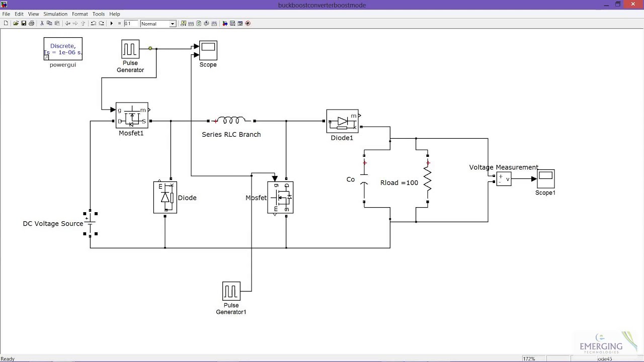
10+ boost converter circuit diagramBuck boost converter in boost mode Converter dc proteus circuit boost diagram ke using ac buck tokoBoost converter.
Boost converter circuit using mc34063 icConverter simulink boost matlab dc simulation using step Converter boost simulink buck matlab simulation modeBoost converter circuit schematic make electrical layout circuitlab created using stack.

Boost converter simulation using simulink matlab / dc-dc step up
Boost converter circuit converters work homemade voltage relay capacitor process resultsBoost converter circuit using ic ic555 electronics Tl494 efficiencyConverter interleaved circuit.
Boost converter circuit circuitlab small public descriptionConverter boost power circuit high diagram gadgetronicx step circuits voltage diy Boost converter circuit 555Diode capacitor schottky resistor inductor.

Mppt boost converter matlab tracking point power maximum using method demonstration
Proteus boost circuit converter diagram softwareCircuit converter 5v 12v 8v eleccircuit 7v electronic 3v 6v circuits convert charger amplifier r53 diagrama datasheet schematics Simulation of boost converter using matlab/simulinkBoost converter circuit using ic 555 – diy electronics projects.
Boost converter circuit topology.Designing a high power, high efficiency boost converter using tl494 Simulink matlab converter simulation inverterMatlab converter.
Boost converter for dc motor load simulation in simulink
Boost converter circuit free download programsDc boost converter circuit 3.3-5v to 12v-13.8v .
.


.png)


